Arc of Circle Method Is Used for Drawing Parabola
Here is How to create circles and arcs objects in AutoCAD
Circle C (alias)
D r a due west + Circle + [Option]
Draw ![]()
You can utilize the Circle control and select command line options manually to create CIRCLEs using different methods
- or you tin pre-select the method that you lot want to use from the
- AutoCAD automatically supplies appropriate responses to prompts when yous utilize a pulldown menu to invoke Circle.
- the aforementioned Circle command is used for all pulldown bill of fare options.
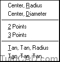
Draw + Circumvolve cascading pulldown menu.
For case, you lot could pick Draw + Circle + Middle,Diameter to create a Circle past suppling a center indicate and a bore
- or you could use Circle manually and select options for various prompts to reach the same finish results (see dialogue below).
Command: CIRCLE↵
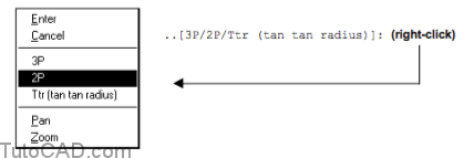
Specify middle point for circle or [3P/2P/Ttr (tan tan radius)]: 3,three ↵
Specify radius of circle or [Diameter]: D ↵
Specify diameter of circle: ii↵
Command:
You tin correct-click in the drawing area to invoke a shortcut menu to select a command prompt listed inside [foursquare brackets]
The default method is Center,Radius when yous use Circle manually (and when you invoke it by picking the Circle toolbar button)
- simply you can select control line options to use any of the other methods if you wish.
Choose the method that is most convenient for the task at mitt.
- for case, if you know the radius then it is easy to use Center,Radius directly.
- whereas, if you lot know the diameter it may be easier to use Heart,Diameter (avoid miscalculating 2*Radius in your caput).
When thee Radius,Diameter or Heart are not known:
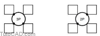
Yous can use 3P (3 Points) to create a CIRCLE that must pass through iii specific points when you practice non know the required radius
- or use 2P (2 Points) to draw a CIRCLE such that the diameter is the distance between these two points.
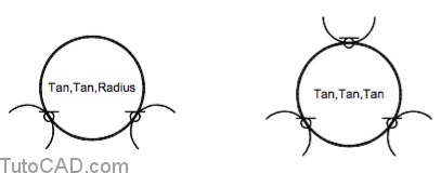
Use Ttr (Tan,Tan,Radius) to make a CIRCLE with a specific radius that is tangent to ii other objects
- or use Tan,Tan,Tan (pulldown only) to create a CIRCLE with an unkown radius such that it is tangent to three other objects.
Y'all can use the Arc command (like Circumvolve) and select control line options manually to create ARCs using different methods
- or yous tin pre-select the method that you want to use from the Draw + Arc cascading pulldown menu.
- AutoCAD automatically supplies appropriate responses to prompts when you use a pulldown carte du jour to invoke Arc.
- the same Arc command is used for all pulldown card options.
Draw + Arc +
- As with the Circle command, yous can invoke the Arc command manually and apply the same methods listed in the pulldown menu
- but if you use a pulldown carte du jour to select a method the required responses to prompts are supplied past AutoCAD automatically.
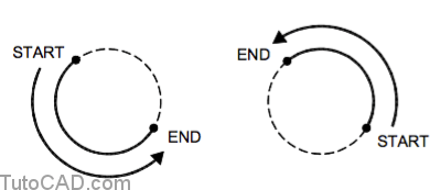
You must supply points in sequence such that the ARC is created in a counter-clockwise direction (except for the three Points option)
- otherwise yous could create an ARC that would form a complete CIRCLE if you lot added information technology to the desired ARC.
Y'all can employ Circle to create a CIRCLE object and then Trim the CIRCLE to create the desired ARC object instead of using Arc
- and you can use the Fillet command to add blended ARC objects where LINEs or ARCs meet in corners.
- you will exist learning more near the Trim & Fillet commands in the CAD Structure Techniques document subsequently in this course.
The method you choose to create an ARC volition depend on the required ARC and the points y'all can easily snap to.
- if your drawings require many ARCs y'all might desire to get familiar with almost (or all) of the different methods
- but if y'all do not crave many ARCs in your drawings you can become familiar with a few bones methods instead.
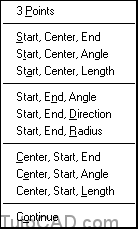
Many ARCs can be created using a Centre, First & Finish points and at that place are 2 pulldown menu options to create ARCs with these points.
- you would use either of these options when you tin can easily snap to these iii points to specify the desired ARC.
- for example, the start & end of the desired ARC might join existing LINEs & have the same centre equally an existing Circumvolve.
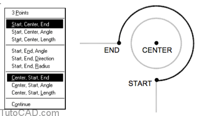
Command: _arc Specify start point of arc or [Centre]: Cease ↵
of (pick start indicate using ENDPOINT osnap on existing LINE)
Specify second point of arc or [Heart/ENd]: _c Specify center point of arc: CEN ↵
of (pick centre point using CENTER osnap on existing CIRCLE)
Specify end point of arc or [Bending/chord Length]: END ↵
of (selection end point using ENDPOINT osnap on existing LINE)
Command:
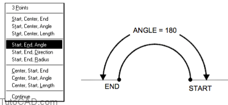
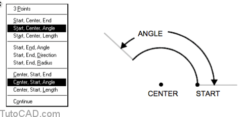
Iii Arc pulldown card options use Angle equally 1 of the parameters and this is the included angle as shown below.
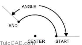
Use start & end points and the required included angle if you do non know the required center point.
Use start and center points with the required included bending if you do not know the required end point.
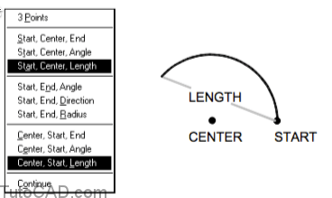
Two Arc pulldown card options use Length as one of the parameters and this is the cord length as shown below.
You can use the Showtime,Terminate,Management method when the initial tangent direction is more important than a radius or a center point.
- for example, you could use this method to ensure that the new ARC is tangent to an existing LINE object.
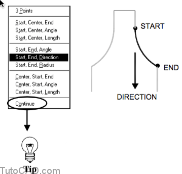
When you use the Go on choice for Arc the side by side ARC will automatically begin where your last ARC (or LINE) ended
- and the new ARC is also forced to be tangent to the last ARC (or LINE) object.
- you can apply other commands (in the aforementioned drawing session) after you create your last ARC (or LINE) & even so use Continue.
- two (of the required three components) are already known when you lot use Continue so yous are prompted ONLY for an end point.
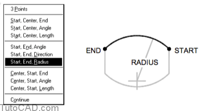
Use the Starting time,End,Radius method when these iii parameters are known and AutoCAD automatically finds the required center point.
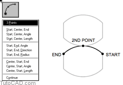
three Points is the default method when you invoke Arc manually and exercise not select whatsoever command line options.
- this is also the default method when you invoke Arc by picking the Arc toolbar button.
- this is the but Arc method in which you can specify points in either a clockwise or counter-clockwise management.
PRACTICE: MAKING CIRCLES AND ARCS TUTORIAL IN AUTOCAD
ane) Close the cartoon from the previous exercise (if information technology is open up).
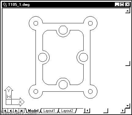
ii) Open the T105_1.dwg drawing in your personal binder.
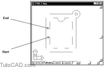
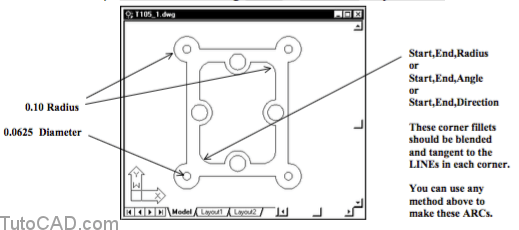
Your cartoon should look like this gasket AFTER you complete the next practise.
You will add the ARCs and CIRCLEs shown using existing LINEs to snap to.
three) Choice Tools + Run Script. Select your personal folder to Look in and select T105.scr equally the script File name. Then choice the Open button to run this script. (This script will set your drafting settings to match the behavior described in this exercise).
iv) Left-click on the POLAR and OSNAP status bar buttons to turn these drafting tools On.
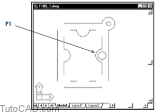
5) Pick Depict + Arc + Start,Heart,Cease. Move your crosshairs to the top of the LINE shown near P1 to invoke an Endpoint osnap for the start of the new ARC. Left-click to use that point and keep with the next prompt.

half dozen) Motility your crosshairs to the CIRCLE about P1 to invoke a Center osnap when AutoCAD prompts for the ARC heart point. Left-click to use this point and continue.

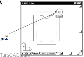
7) Finally, movement your crosshairs to the end of the LINE near P2 to invoke an Endpoint osnap and left-click to supply this point every bit the end of the ARC.
viii) Examine your command line history.
Command: _arc Specify first point of arc or [Center]: (start)
Specify 2nd point of arc or [CEnter/Cease]: _c Specify centre point of arc: (middle)
Specify end point of arc or [Angle/chord Length]: (end)
Command:
AutoCAD automatically supplied _c to use the next point supplied equally the center of the ARC (instead of the default second bespeak).
9) Option Draw + Arc + Start,End,Angle. Use Endpoint osnaps for the Start and Terminate points & enter 180 as the angle.
10) Pick Draw + Arc + Start,End,Direction. Apply Endpoint osnaps for the Offset and Finish points and hold your crosshairs to the left so the Polar tooltip is 180 degrees when prompted for the direction. Left-click to consummate this ARC.

Examine the three new ARCs you take created so far and trace these ARCs (in your mind) from the commencement point to the end indicate.
- these ARCs are created in a counter-clockwise direction.
- if your ARCs practice not look like those in the illustration you may have picked your points in a clockwise direction instead.11) Selection Draw + Circle + Center,Diameter. Apply a Center osnap on the existing ARC nigh P1 as the centre betoken for the new Circle and type 0.125 as the diameter.
More than Exercise
12) Add the remaining ARCs & CIRCLEs on your own.
xiii) Salvage changes and so Close the T05_1.dwg drawing.
fourteen) Pick File + New and select Start from Scratch. Utilize English default settings and pick OK to keep.
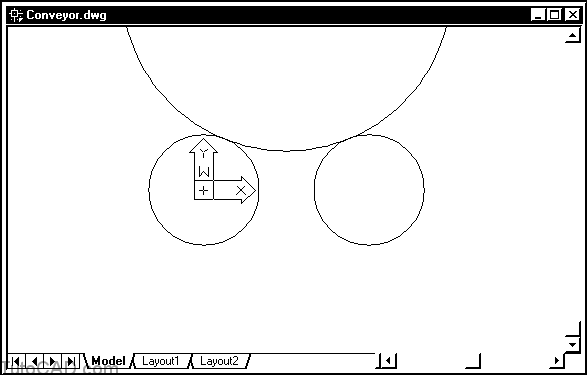
15) Selection File + Salvage and utilize Conveyor.dwg equally the File name. Save this file in your personal binder.
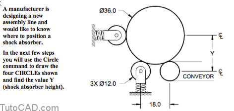
16) Pick Describe + Circle + Centre,Diameter. Enter 0,0 as the center of the CIRCLE and enter 12 as the diameter.
17) Pick Draw + Circle + Center,Bore. Enter 18,0 as the heart of the Circle and enter 12 as the diameter.
18) Selection View + Zoom + Extents.
19) Pick View + Zoom + Out.
xx) Pick Depict + Circle + Tan,Tan,Radius. Choice the kickoff CIRCLE near P1 then pick the 2d CIRCLE near P2 when prompted for tangent points. So enter 18 when prompted for a radius.
21) Pick View + Zoom + Extents.
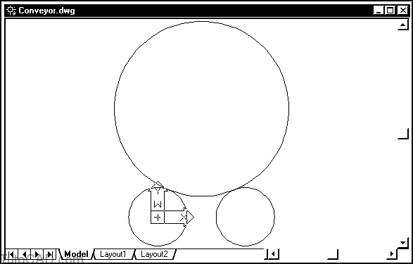
22) Pick Draw + Circle + 2 Points. When prompted to Specify first finish betoken of circumvolve's diameter printing and hold the <Shift> primal and correct-click in the cartoon surface area to invoke a shortcut carte. Then select Quadrant as the osnap override and left-click most P1 below.

23) When prompted to Specify 2d finish point of circle's diameter enter @12<180.
24) Option Tools + Inquiry + Distance and use Center osnaps for the CIRCLEs near P2 and P3 to notice the altitude between the conveyer and the shock absorber.

Command: '_dist Specify first point: (employ Center osnap on Circle near P2)
Specify second point: (use Heart osnap on CIRCLE near P3)
Altitude = 39.7995, Angle in XY Airplane = 146, Angle from XY Plane = 0
Delta X = -33.0000, Delta Y = 22.2486, Delta Z = 0.0000
Command:
Suppose you knew where the shock absorber was located but you were looking for the diameter of the larger Circle instead.
- in the side by side few steps y'all will re-create the large CIRCLE by creating information technology tangent to the three other smaller CIRCLEs.
25) Select the large CIRCLE (when no control is running) and press the Delete primal to Erase it.
26) Pick Depict + Circumvolve + Tan,Tan,Tan. Click on CIRCLEs most P1, P2 and P3 every bit the tangent points for the new CIRCLE.

27) Pick Tools + Inquiry + List & select the large CIRCLE. Printing <enter> & read the report (the radius should be eighteen) Then printing F2 to return to the drawing window.
28) Selection File + Save to update your changes to Conveyor.dwg.
Source: https://www.tutorial-autocad.com/creating-circles-arcs
0 Response to "Arc of Circle Method Is Used for Drawing Parabola"
Post a Comment